
This VSWR analyser looked interesting from K6BEZ. Certainly simple and low cost and probably just the thing to test the multiband SOTA antennas that I have been putting together lately. I happened to have one of the DDS modules spare and would change the Arduino module in the article to a Nano as they are compact and cheap (~$10).

Screenshot
Rather than build it on veroboard as per the article, I made a PCB using Eagle and the toner transfer process. The board is mostly SMD to keep it compact and these days SMD is easier anyway.

Analyser PCB
The board came out nicely, it is single sided and only has one link. It uses the entire bottom copper as a ground plane. I couldn’t source the AA143 germanium diodes locally, so picked up a couple of 1N34a diodes.

Assembled Antenna Analyser
After loading all the parts with the exception of the MCP6002, I got a little impatient and plugged in an LM358 temporarily so that I could play a little. I remapped the DDS data lines on the Arduino to better suit a simpler PCB layout. It all went together pretty well. Another compromise made was with the gain resistors on the op-amp. I didn’t have any 5k / 648 R resistors, so the gain was kept the close by using a 6k8 and a parallel combination of 1500 and 2200 R resistors (891 R). This gives a gain ratio of 7.624, where the original resistors had a ratio of 7.716. After a power up, it looked OK, so the K6BEZ analyser software was started. It connected OK, and when the sweep command was executed, you could see comms activity, but there was no display on the graph. After poking and proding, I could see that the DDS was indeed sweeping and there was a slight analogue voltage sweep to the Arduino. As a last resort, I tried an older version of the sweeper titled “Thrifty Antenna Sweeper”. This sweeper did give a plot on the graph although it did not redraw on every sweep. A dummy load was connected and there was a more or less straight line. The offset fed HF dipole was connected and the resultant sweep did sort of show dips where there should have been. I will wait until the MCP6002 arrives before doing anything else. The MCP6002 op-amps arrived today. Once installed, they fixed what seemed to be an DC offset problem where the SWR on a 50 Ohm load was 2:1. Now it seems that there is a frequency response problem with the substitute diodes (1N34A). See plots below:

No load on the analyser

50 Ohm load on the analyser

OCF antenna with 50 metre old RG58 extension
Note-that the OCF antenna used for the test was extended with a 50m+ run of RG58 coax to reach the computer, so the coax run is probably making the match look a lot better than the antenna is at the feed. Next thing is to obtain the original diodes (AA143) to see if that is the reason for the falling response. Yahoo_Group: https://groups.yahoo.com/neo/groups/k6bez_projects/info Update 2014-09-30: Beric, K6BEZ replied on the yahoo group with a fix to the aduino code to make it compatible with the newer PC sweeper software. // Send current line back to PC over serial bus
In summary, there is an unused field that has to be removed for the newer sweeper software and the FWD and REV fields are not used.
Update 2014-09-30: 1N60 diodes made a noticeable improvement over the 1N34a diodes. There is still a rolloff in the plot when the analyser is unterminated, but VSWR is now reported out to 30MHz that correlates with the VSWR measurements using a bridge.
Update 2014-10-05: The analyser was hooked up to the SOTA End Fed Half Wave to see how it looked. A 10m feed of RG58 was used. The result is pretty good. It seems to be working OK now. The antenna was originally optimised for 7.090 MHz and it is damn close in the plot.

40m End Fed Half Wave

Original K6BEZ circuit with Arduino ports changed. Note R4 shown as 50R it should be 10k
Update 2014-10-10: Changed R6 on the DDS board from 3k9 to 2k2 which resulted in an increase in DDS output. With 3k9, the output loaded to the sweeper was 600 mV p-p. With the 2k2 the output increased to 1000 mV p-p. This change increased the sensitivity of the analyser noticeably.
Some plots from the 40/20/10 metre end fed: 


 Update_20114-10-08: The PC program won’t run on my Windows XP netbook, which makes it difficult to do measurements outside.
After some software programming using processing, I have a multi-platform capable application that will at least run on the old netbook. The application is pretty rudimentary, but plan to work on it and clean it up a bit. At present it will only sweep a few pre-defined ranges as the graphing is rather basic. I am using the grafica graphing library for processing to do the plotting.

EFHW – Plot
Here is a plot from a 40m end fed half wave. The processing application is working pretty well now. I have divided the sweep into 3 bands, 1-10 MHz, 10-20 MHz and 20-30 MHz. This was pretty easy to scale. I might add the HF ham bands later.
It does run on the old XP netbook just fine.

Packaged up
Update 2014-12-06: Lars, KN5UTE did a great job of cleaning up and enhancing the user interface on my processing version of the sweeper software. The com port can be selected now where as before it just chose the first com port it came across. It still won’t compile to an .exe for some reason, so it is still running out of the IDE.
The VK3YY/KN5UTE software can be found the software is in the files section of yahoo groups “K6BEZ Antenna Analyser”.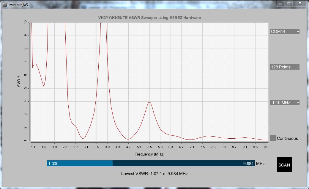
Update 2015-01-04: Received some AA143 diodes in the mail from KN5UTE, tried these out and there was a slight improvement at the 30MHz end compared to the 1N60A diodes.
I will leave these in.


Thank you for your extremely helpful blog post. Though I’ve never built electronics before (no less solder) I’m going to try to source the materials and build this for myself. If you have a bom, could you make it available on your dropbox? Also, forgive me if this is an extremely naive question, but what is the white [thing] (is it a wire/resistor?) next to the diodes. I looked at your schematics and can’t find a reference for it.
Thanks in advance!
Good question about the white thing! It is just a wire link with some insulation over it so that it doesn’t short to the tracks that it bridges. It does look like a component though. I don’t have a BOM unfortunately. Cheers, Glenn.
Hi Glenn!
The connectors are labeled SV3 what is its role? Connect any external source of energy?
Thanks in advance!
Hi, I am pretty sure that the connector is just there for testing. The analyser gets its power from the USB connector
ThanksVK3YY and Lars. I use linux system and open jdk. Control P5 is 2.2.5 ver. I have resolved a few issues with trial and error. Now the serial port selection is giving a large number of errors in the console. Same way all dropdowns are producing a number of errors. Let me try some other Java. I will let you know about the changes once it works.
This is the console output. Can you guess something from it.
ControlP5 2.2.5 infos, comments, questions at http://www.sojamo.de/libraries/controlP5
Sep 04, 2015 5:35:07 PM controlP5.ControlBroadcaster printMethodError
SEVERE: An error occured while forwarding a Controller event, please check your code at controlEvent
java.lang.reflect.InvocationTargetException
at sun.reflect.NativeMethodAccessorImpl.invoke0(Native Method)
at sun.reflect.NativeMethodAccessorImpl.invoke(NativeMethodAccessorImpl.java:62)
at sun.reflect.DelegatingMethodAccessorImpl.invoke(DelegatingMethodAccessorImpl.java:43)
at java.lang.reflect.Method.invoke(Method.java:497)
at controlP5.ControlBroadcaster.invokeMethod(Unknown Source)
at controlP5.ControlBroadcaster.broadcast(Unknown Source)
at controlP5.Controller.broadcast(Unknown Source)
at controlP5.Controller.setValue(Unknown Source)
at controlP5.DropdownList.onRelease(Unknown Source)
at controlP5.Controller.setMousePressed(Unknown Source)
at controlP5.ControllerGroup.setMousePressed(Unknown Source)
at controlP5.ControlWindow.mouseReleasedEvent(Unknown Source)
at controlP5.ControlWindow.mouseEvent(Unknown Source)
at sun.reflect.GeneratedMethodAccessor4.invoke(Unknown Source)
at sun.reflect.DelegatingMethodAccessorImpl.invoke(DelegatingMethodAccessorImpl.java:43)
at java.lang.reflect.Method.invoke(Method.java:497)
at processing.core.PApplet$RegisteredMethods.handle(PApplet.java:1398)
at processing.core.PApplet.handleMethods(PApplet.java:1593)
at processing.core.PApplet.handleMouseEvent(PApplet.java:2678)
at processing.core.PApplet.dequeueEvents(PApplet.java:2601)
at processing.core.PApplet.handleDraw(PApplet.java:2412)
at processing.awt.PSurfaceAWT$12.callDraw(PSurfaceAWT.java:1499)
at processing.core.PSurfaceNone$AnimationThread.run(PSurfaceNone.java:312)
Caused by: java.lang.ClassCastException: controlP5.DropdownList cannot be cast to controlP5.ControlGroup
at controlP5.ControlEvent.getGroup(Unknown Source)
at sweep2.controlEvent(sweep2.java:223)
… 23 more
After some more tinkering I managed to run the sweeper. I will send it on email. It is the new controlP5 library expecting different ways to handle the event handlers.
OM VK3YY,
I did upload the modified version of your processing code on the yahoo group for K6BEZ antenna analyzer under VU2SPF folder with your original notice, and without adding my info anywhere in the sketch. I don’t know if your permission was needed. In case you have any objection to my upload, I will remove it and do as per your instructions. I apologize if I have trespassed on your rights somewhere unknowingly. I could not find your email anywhere, so putting up this message here.
VU2SPF
Hi, ok on the upload. My permission is not needed to upload a file to Yahoo groups files section as I have no control over the content of that group. I have no objection to posting modifications to the sweeper processing code to Yahoo groups. Lars has made significant improvements to the original code and good to hear you have it running on a Linux platform.
Thanks for your kind gesture in true ham spirit. I have also added another slider for VSWR below the one for freq. That helps when your antenna is well tuned or when VSSWR is small.
By the way, any plans to add an amp before the bridge to improve sensitivity? I found one at http://www.pongrance.com/dds-buffer.html and used in one of my arduino dds. It gives signal of 5Vp-p, which should be enough for this analyzer.
Hi, no plans at this stage to add an amp, the analyser works fine for my needs, great on the extra slider.
Did you ever change from the 1n60 diodes to the aa143’s?
Hi Kevin, yes I did change them to AA143s. There was a slight improvement at the 30MHz end over the 1N60 diodes.
Thanks for the reply – I saw that you had done so (after I realized I was searching for AA123 instead of AA143). I’ve ordered the 1N60’s – I’ll get the AA143’s if I’m not happy.
what is the maximum frequency?
30MHz as built.
1N60A or 1N60P? there are two versions …
1N60A or 1N60P? there are two versions …AA143 is hard to find
I used 1N60A.
Cheers,
Glenn.
Glenn
Trying to put a club project together and finding analyser is showing lower readings than MFJ analyser, the ‘dip’ agrees but the higher ends of the curve are not as high as from the MFJ. We have used 1N34 diodes and then 0A47 with some improvement. 1N60 diodes on order. Have you compared your unit with a commercial analyser?
Hi Steve,
Will be interested to see how your 1N60 diodes compare. The analyser is not that accurate in absolute VSWR, presumably due to the linearity of the diodes and operating at their lower forward voltage range. I did some plots with 50 and 100 Ohm resistors and noted a departure from what it should have read.
Hi Glenn
On the PCB are there 3 holes, with no components, are these three holes link to the bottom curcuit ?
Hi Lars, I added an image at the end of the article that shows the holes that are links to the ground side of the PCB, this should explain it.
Excellent project. Congratulations. LU4EOU, Mario
i have an idea.

i have a SWR Bridge purchased from ebay.
http://i.ebayimg.com/images/g/PdwAAOSw7ThUeqfO/s-l300.jpg.
Why we not we use the same in place of swr bridge in circuit?.This will eliminate some headache due to availability mcp6002 and aa143 etc.
Hi!
I build one. Working well.
648OHM (R7,R11) combined with 13K+680OHM in parallel. I was miss the comment that R4 must be 10K. I spent few ours to find the error.
Thank you for project description.
Great to hear it is working !!!
In the article you write: “Update 2014-10-10: Changed R6 on the DDS board from 3k9 to 2k2 which resulted in an increase in DDS output.”
I can’t find the R6 with 3k9 in your schematics can you tell me again which resistor you changed?
or where I have to search for the R6? 😀
If you click on the photo of the analyser pcb with the DDS module on it, towards the lower right end of the DDS module you can see the part labelled R6.
I guess I have a different DDS board. Do you have the schematics of your board so I can figure out, which resistor I have to change on my module?
Hi Julian, I have emailed the schematic to you.
I have drawn up a circuit diagram that shows the two common dds boards available from ebay and other places on the net, as i had to find the schematics and substitute into the circuit. If any one is interested in that circuit diagram drop me an email. I too am interested in this fix as my dds board drops off at 24 Meg but I cant find a 3.9 k resistor anywhere on my DDS board except at the I-R pin. Is that the one that has been changed in this fix? Terry M
I know that this is a long shot, but I’ve hooked everything up correctly (AFAIK) with this AD9850 & an Arduino Uno (using the NR8O website as a guide). But, I seem to get no output (I used a frequency counter and a wire as an antenna, using an SDR to see if any signals are present in the room). I have power to the AD9850 but debugging seems to be tough
Any suggestions on troubleshooting?
Kevin – I had to trouble shoot my project as well.
1. I hooked a cro to the ad9850 sine wave output. Make sure that it gives a clean sine wave first. ( There are lots of places on the net to make a circuit to just check the ad9850 works) Most problems here could be the connection to the data,clock,reset,update pins – check you altered the clock and update wires which were originally shown the wrong way around. Make sure also that the connections go to the right pins on the uno. I had some problems with a uno and replaced it with a Leonardo.
2. Then found that I had to put a 1mf electrolytic capacitor in at c1. The 2*470 nf didn’t work. This gave a clean sine wave at the output side of c1 but a saw tooth wave at the antenna output. The graphs produced were inconsistent – see my other post.
3. Next I had substituted the 50 ohm resistors with 56 ohm ( R1,2,3 actually a little higher value). When I substituted 2 * 100 ohm paralled in each place to make 50 ohm the output signal cleaned up to a sine wave. I then replaced c2 and now have a lovely clean sine wave at the antenna output as the sweep is executed.
4. I find that the sweep sine wave out put decreases rapidly after 24 MHz and my unit does not give a good reading on the 10 meter band. I think because the output from the ad9850 drops to under 1 volt p-p. However the graphs now on each sweep are consistent and show the swr dip in the same place each time.
I would love to try against a professional antenna analyzer to see the difference as this project makes a great unit that really works.
Thanks to all concerned for the circuit design and the software production. Your time in production and sharing is greatly appreciated. Maybe my building and trouble shooting experience can be helpful to someone else. Terry M – VK4ATM
Thanks for the great info here. This is a Great project – love the DDS modules.
I have completed the build of the Antenna Analyser after some trial and error and have the Pcsoftware code running. So many different versions of the DDS sweeper code from various places that it was hard to find the latest two that interfaced together on a Pc. Maybe some one could confirm the latest code parts (i.e. the ino file and the Pc interface software – the one with the big blue scan button at the bottom right.)
The code gives great control of the AD9850 – watched the sweep on a cro and it gives a smooth controlled frequency shift – the sine wave is very stable, clear and clean. The data is returned and a graph produced – However, when I run the code the sweep returns a different set of values for each time the sweep is executed. I have checked the code and the circuit now several times. Odd I dont get a wave form at the antenna socket that is a clean sine wave it is a saw tooth shape. Should it be – does anyone have a screen shot of what the output at the antenna socket should look like?
I found that the 1 microfarad electro capacitor that I had substituted with 2* 470nf ( total .94mf) ones in parallel didnt work well and it has made some difference when removed and a 1mf electro fitted. Each sweep now gives a graph with dips in much the same place each time. Still the swr readings returned are quite dis-similar each time a sweep is run. Does any one have any thoughts?
The only other parts substituted were 56 ohm resistors for the 50 ohm resistors – will try 2 * 100 ohms to get a closer approximation tonight and see if that makes a difference.
Appreciate all the thoughts here. Terry – VK4ATM
Question on your setup – do you get a 1:1 reading if you are driving a 50 ohm dummy load? I just built something very similar and am trying to figure out if it is working – but am not getting 1:1 there.
Hi Ben,
Yes, I get a close 1:1 reading into a 50 Ohm dummy load.
Basic questions from a new microcontroller enthusiast:
1. Do you need to upload additional code to the Arduino to make it display on a PC as long as the sweeper program is downloaded onto the PC.
2. If I decide to use an LCD instead of a PC, do I need to upload additional LCD code to the Arduino, or is it included in the Arduino code that is posted.
3. Can I use a Raspberry Pi 3B with it’s display instead of a PC. If so, do I need to upload additional code to either.
4. Since the Arduino only runs the last code uploaded, how can I upload any additional code that might be necessary for the display, if it’s not included in the main Arduino project code.
5.I am assuming that the usb port on the Arduino is used for connection to the PC or raspberry Pi. Am I correct.
In other words, I understand the project and the concept, but, being new to microcontrollers, I am very confused about how to display my SWR information. Sounds like a great project for an old extra-class operator who is trying to “modernize his electronics knowledge base. Heck, I started out with vacuum tubes, ha ha!
Hopefully I’ve expressed my questions intelligently enough for you to understand what I’m after. Try not to laugh too hard!
Congratulations on an excellent, and apparently very popular project
Bill Neely, KE5K
Hi Bill,
OK on your questions, answers are:
1. Yes, there does need to be Sweeper code in the Arduino in addition to the PC software.
2. Yes, there will need to be specific code in the Arduino to drive an LCD display.
3. Possibly, but you will need software to run on the Pi to interpret the data from the Arduino.
4. You will need code that does the sweeper and the LCD together.
5. Yes that is correct.
Your questions all make sense and understand why your are asking!!
Cheers,
Glenn VK3YY.
Thank you, sir. I will get to work straight away, Hopefully I an pull this one off without too much bungling. I appreciate the speedy reply, It is most obvious that you are a fine gentleman. Have a great week, and, again, thanks!
Bill
Daft question. Is this a single sided piece of copper board, just printed on one side? also is this the final board for the altered/replaced components?
ta muchly 🙂
It is double sided board etched on one side only, the other side was masked when etched so it is a full ground plane. The final components are not shown on the photo. The op-amp and diodes were changed. Cheers..
I made the same circuit but Through Hole components only. I made my pcb in eagle and got them manufactured in Hong-Kong. It´s a great circuit and runs with Arduino Nano original. I mamaged to get a whole bunch of AA143. Thanks. Cheers 73 Isak SA6VEE
Hi, Thanks again, I got a red vertical line and several blue. The red is best VSWR, but what is the blue lines? 73 SA6VEE
Hi Peter, he only PC display software that I use now is the VK3YY/KN5UTE software and this only has a red line for the plot. Where is the blue line? Do you mean the slider line at the bottom? Which display software are you using?
Cheers Glenn.
I am using the K6BEZ software. The blue lines are apearing vertical. Where can I download the vk3yy/kn5ute software. Do I need to change the arduino sketch or hardware? Otherwise the sweeper works great.
Hi Peter, the vk3yy/kn5ute software is in the files section of yahoo groups “K6BEZ Antenna Analyser.” I should put a link on this blog. The code on the blog works with the vk3yy/kn5ute software.
The blue lines are probably markers for the amateur bands.
Cheers,
Glenn.
hi,
here is a dropbox link to a zip file that contains the code. it is a Java executable, that means that although it is an .exe file it relies on java libraries that are also provided in the zip file (linked).
you must leave the .exe in the same relative directory position as the lib folder that contains the java stuff, otherwise the .exe won’t find the necessary libraries and will crash. you CAN however, make a shortcut to the .exe from somewhere else, just don’t move the .exe relative to the lib folder.
good luck to you, it should work fine on xp.
https://www.dropbox.com/s/okwf3uboebtrnxf/sweep.zip?dl=0
if you _do_ have problems with it, the first thing to try is to see if your java installation is current.
r/lars KN5UTE
Thanks Lars! hope all is well over there. I thought there was a link to the code but had a look this morning and couldn’t see one.
Cheers, Glenn.
Congratulation: very good project.
I finished my one last week and it is working very well.
I want to use the same approach to display the filters shape and so I will make the resistors bridge board interchangeable with an AD8307 detector.
What PC program should i use to display the filter respons ?
What modification is needed to the Arduino software ?
Thanks in advance for any suggestion .
Regards,
iw2fvo,
Ambro
Good day ,
I have completed my analyzer last week: congratulation it is a great project.and works well.
There is a point: it locks_up after few minutes if in continuous scanning mode ( win 7 64 bit ).
I have now in mind to modify the circuit by introducing ann AD8307 detector to display the filter response shape.. I plan to make the actual resistor bridge interchangeable with a small detector board. At this point I will have just one analog out to send to Arduino.
>> what program should i use for PC display ?
>> what modification to the Arduino software ?
Thanks a lot in advance for the assistance.
Regards,
Ambrogio
iw2fvo
Hi Ambrogio, are you using the VK3YY/K5UTE PC software? This is the only PC display software that I have been using and it did not have any lock up problems. The Arduino code on the blog is compatible with it, Cheers, Glenn.
This project is really great ( BIG THANKS TO ALL ) – I have built several units. They all worked straight up – oh well after a little troubleshooting but it is very easy to fault find. This works with all versions of Arduino both originals and clones and I have tried 15 – 20. you only need to tweek the code to work. The original mega and mega clones are a little more obstinate than others requiring more code changes.
A problem I am finding is that each unit is different in the figures that are produced.
How can I check the accuracy of the results output from the units?
It sort of defeats the purpose if I have to buy a MFJ etc to check the units that I make.
To explain – I tested by attaching the same antenna to each unit and found that each unit gives slightly to significantly different results in the graphs produced when attached to that same antenna. Circuits all being identical – except for 5% component tolerances.
When I say each unit is different, I mean the basic peaks and troughs are mostly similar but they range quite a bit in the frequency shown and the SWR measured and in some units some peaks or troughs shown from one are not shown in the other. Hope that makes sense to readers.
I have tested the AD9850s and found that they produce the same frequency sweeps to within 200 hz of each other as they sweep. I still need to find out how to tweek the AD9850 to get closer to each DDS module being exactly the same, as it is given the same word to make the output frequency.
I have also been working with the code from here in an effort to make the unit more portable.
So far I have modified it to work with 20 char * 4 line i2c lcd display showing sweep fx, lowest SWR and FX for the SWR, SWR as it sweeps and am working with TFT displays to expand further. Next experiment will be keypad entry to remove further from the laptop. Although I love the big laptop screen graph.
Has any one experimented with the code to run on a TFT display and draw the results there and be willing to share their experience?
Has any one experimented with the circuit to show line characteristic impedance as well as SWR?
Thanks again to all.
Terry M
Hello I did make the analyzer as discribed , and debugging i discovered the 50ohm R4 had to be a 10K , and the newer sweeper software worked from the beginning, fine ,so I used the LM358N and the germanium diodes OA95 old type diodes , and tried several LM 358N to see of there was any offset between them no
difference , all the same readings ,
So I tested the scale .the SWR reading is bij 50 ohm sure 1:1,0 , but with 100 ohm there should be a reading of 2 : 1 , and and with 200 ohm 4 : 1 but the readings are 1.24 and 2.4 : 1 ,
open input gives 15.8 : 1 , should be very high or infinity.
has this something to do with the offset of the LM358 ?
Is the MCP6002 a needed one for the scale SWR ,
also there is no cw signal working in the software Newer Sweeper
I hope you will suggest or help me out to understand the scale misalagnment
Peter PA0PVL
HI Peter
The things you have found here are the same as i am working with at the moment. I surmise that the LM358 has it been substituted for the MCP6002?
I have found that the voltages supplied from the ad9850 make a difference to the swr readings.
I placed a broad band buffer amp after the 1mf capacitor and have a different set of swr readings. Much higher swr readings and much deeper troughs. It also helps the frequency readings above 15 mhz to be more pronounced.
I am examining the code at present to see how the SWR is calculated from AO and A1 on the arduino.
Its back to the books to understand the maths for the calculations and how the bridge works.
I would be interested in sharing any thoughts or information that you find.
Terry M
VK4ATM
I have been looking at what a lot of others have been doing and you might like to look at
http://blog.riyas.org/2015/04/a-simple-standalone-antenna-analyzer-with-ili9341tft.html
Some interesting additions
Terry M
VK4ATM
Thanks for the link, great stuff!
i will like to remove the diodes and the two op amplifiers and replacing them with a couple of AD8703 detectors. What do you think about ?
thanks,
73, iw2fvo
Hello I did make a RF meter with the AD8703 and in a little box it is working as a HF sniffer , advantage of the IC is it has a great range in logaritm scale in dB ca 60 to 80 db, so this is better
in a arduino measure analyser , very small IC ,must be shielded in a separate box from the Arduino noise ! ( Getting no valse readings )
Peter Pa0PVL
Sounds great, that chip should make the antenna analyser much more accurate!
Sounds like a great idea, you should get much more repeatable and accurate performance.
just to be sure of my circuit operation: what is the voltage at the DDS output ?
What is the voltage at the two transistors amplifier output ?
I have also find that the ampl out goes down about 10 dB at 30 MHz: is it normal ?
Thanks for helping.
73, iw2fvo
Hi, one of the weaknesses of the design is marginal output from the DDS. I am not at home at present, so cannot check notes or the unit itself. A broadband amp after the DDS would improve performance and keep the diodes operating in a better region.
Yes I agree Terry , i’ll build a MMIC amp , a MAR 3 wil ampifly a13 dB , so we can see the
difference in the liniair piece on the diode char.
I’ll keep in touch
Peter PA0PVL
could someone post the schematics for the connection of the two AD8703 detectors please ?
thanks for all.
iw2fvo,
Ambrogio
I think this is going the right direction. I tried using 2 bc547s for the broadband amp but they demonstrate some odd wave forms out – even disappearing at certain frequencies. Started adding the unit to a TFT screen. What an interesting experiment. So many different TFT screens and they all seem to need different drivers and different wiring for the same chip sets.
Keep up the good work. Terry M VK4ATM
This drop seems to be normal for the DDS modules that I tried.
The voltage PEP goes down gradually as the frequency output increases. Some DDS modules are better than others and some are different in frequency output with the same code word sent.
I have been trying to get a consistent voltage output for the full range 1-30mhz but am beginning to think that it may need to be broken up into segments to adjust for consistency.
I find that the graphs produced start really well – the peaks and troughs show well but at higher frequencies it drops (gradually above 15 mhz). I am sure that is from the DDS module output level. A buffer amp produces much higher peaks and troughs across the entire range of frequencies. It has to if you look at the formula that calculates the display swr. (fwd+rev)/ (fwd-rev).
Terry M VK4ATM
Hello Terry
Yes I would like to share the discovery’s i make on the arduino nano analyzer ,
I found a artikel or note on internet by Billy.gr he write something similair about the SWR readings and scale , thanks for coming back at my comments, i will look to the DC levels at a load 50ohm
there should be max on FWD en zero at REFL output from the SWR bridge and
by open antenne connection Max DC on both , in ihis link from Billy.gr ther is a piece about the
reference dc of the Arduino Nano , http://www.billy.gr/antenna-analyzer/
It is strange to communicate with you there at the other side of the world sleeping , and otherwise
i am sleeping.
The only way i made contacts with VK was using WSPR , here from PA Holland.
oke i keep contact or send some foto’s over email.
Peter PA0PVL
Hello all
Well I am convinced that the output DDS must be more for more working in the liniair area of the diode ,so amplifying the DDS O/P to max ADC level to arduino ( 3.3 V no more!) by open input antenna input.
here I replaced R10 with a 10 kohm potmeter and found a point for 3 : 1 SWR by 150 Ohm,
at the antenna input 50 Ohm ,is still 1 : 1 , but the scale is more or less dependent to the diode characteristics , wel first amplifying then and looking for better diode working-point.
for now to busy with the grandchildren and family.
Peter PA0PVL
o/p two AD8307’s to A0 the other To A1 arduino (stay under 3.3 adc voltage!)
so oke ? for IW2FVO
hgr Peter
Hi Peter, yes, you are correct, the output from the DDS is marginal at best. It can be raised slightly with a resistor change, but the best approach would be a gain stage after the DDS.
Yes you are right I made a amplifier and did correct the gain for high 30mhz and gain up to 0 dBm
and so it is better, i got interested for a AD8307 dB liniair detector and made a better and wide range detection and a return loss bridge, thanks for the interesting project.
I see the instructions say you can replace the AD board with a SI oscillator for “higher frequencies”… I see this setup all over…has nobody ever done/documented something similar that would work for VHF/UHF?
Hi Justin, it should work, the SI clock generator produces more output than the DDS, so it would be a good approach. The layout would become more critical than the HF sweeper.
Hi Glen,
Thanks for the write up, I could not have built it without your excellent instructions, however I have found a small problem.
After I built your design of the antenna analyser I have had problems getting it to give me a vswr of 1:1 on a 50 ohm dummy load. I originally put some correction factors in the code. This was fine until I went to test my antenna on 20m wavelength. I started getting minus numbers in the csv I had produced from the test in the VSWR column.
A few hours of digging and experimentation led me to an error in the code for the arduino mini.
The initialisation of the FWD and REV variables turned out to be incorrect.
How it works is that arduino will return a number between 0 and 1023 whenever you do an analogRead() call to a pin, the number depends on the voltage present at the pin. When the variables were initialised as a double it was causing an issue because when cast back to an int again it will cause an integer over run fault and a negative number will result.
Once I had changed the code so that FWD and REV were initialised as an int everything was suddenly working and my testing with a dummy load produced a VSWR of exactly 1 every time.
The lines that need changing are lines 118 which should read int FWD=0; and line 119 which should read int REV=0;
I hope this helps the accuracy of the analyser.
73,
Dave VK5FFAU
Hi Dave, great find. I have often seen the VSWR swing wildly on the plot under certain conditions, your fix matches the symptoms. I think that Lars, KN5UTE mentioned of a similar error in the arduino code.
I tryed to changed the code as you wrote. but the outcom was not good. The graf is not smooth any more. It looks like squeres. So I am back on the original ino file again.
A further follow up regarding the negative numbers, I noticed in subsequent testing that a negative number would pop up every now and then when ever VSWR climbed above 32 ish. I noticed the cast to int was also making the integer over run and causing a negative number. The fix is to cast to long instead of int
The line concerned is line 153 where it says Serial.println(int(VSWR*1000));
I modified it to read Serial.println(long(VSWR*1000));
see here for the arduino manual on long –> https://www.arduino.cc/en/Reference/Long
73,
Dave VK5FFAU
Hi Dave,
It tried your change of making the double an int, but the result was truncating of the level so that it had largish steps on the plot, so changed it back. Cheers, Glenn.
Ah, yes… Oops apologies all. I have made a mistake. It should be a float cast and not a long. A long will truncate the decimal point.
No worries Dave.
Hi to all!
Could you please post the final software release ?
Or a link .
Thanks
iw2fvo
Ambrogio
Hi wallgirlforapapertown,
There are only 3 changes to the original code which is found above in the DDS Arduino Code link.
Line 121: the data type needs to be changed from double to int
Line 122: the data type needs to be changed from double to int
Line153: the data type needs to be changed from int to float
If you do the above on the stock code it should all work for you.
I am sorry, I currently do not have a web site and I can’t attach a file here and I won’t paste the whole code in a comment.
Thanks
iw2fvo, Ambrogio
Dave: I do not find any int at line 153.
Just to be sure : will you pls post the whole code ?
my mail: iw2fvo@yahoo.com
Thans for all.
73 , ambrogio
iw2fvo
Hi, you can download my modified code from my personal website here –> http://www.users.on.net/~dtjoyce/DDS_sweeper.zip
I hope you can get it working
73,
Dave VK5FFAU
Hi Dave,
Which program do you use on your PC?
73 de TA1MRT
an interesting project that I would like to do. but I like to solder components on PCB’s rather than holes on a fiber board. PCB’s are much more neater. I have done kits before but have never made a PCB. So where can I get a PCB made?
northriver.se have ready made pcbs.
Thank you for the reply and link. I have a problem. When I click on a link in northriver.se I get a message (could not perform this operation because the default mail client is not properly installed).
I had to replace the HDD in my laptop recently and reinstall windows 7. But I cannot seem to find and or install default mail client, Therefore I cannot open any of the links in northriver.se. Any comments to help would be appreciated to get to the links.
thanks
ken
The email on Northriver.se is sa6vee (at) northriver (dot) se
I wanted to put one of the kits together and I thought the analyzer project was proven and finalized, but It appears from reading the whole thread that this it is still in its infancy. From reading the post it seems many if not all are having trouble getting the analyzer to function properly after following K6BEZ’s design.
Hi, I like the fact that you posted eagle schematics and design. Toner transfer is not new to me. However I don’t understand this, the schematic has lm385N two times and the pcb has it one time. Now I can’t completely make up wich resistor/condensor goes where? What am I overlooking?
txs, ON3JUR 73′
Hi, the design has a dual package chip, so it has two op amps in one package. I used an LM358 first (dual op amp) but later used MCP6002 (same pinout) it is more suited to the application. Glenn.
Thanks, drawing the specs on the board right now, figuring slowly. Could you kindly mention if R11 648 is missing on the picture where the bottom should be soldered? (it is not on the drawing, but it seems connected on the bottom in the print you soldered)
Thanks, 73, ON3JUR, Jurgen,
Hi, I am not sure of the question, is R11 missing from the grounding diagram?
I am just asking good sir, if close to R11 is there a grounding point missing, it is not shown on the diagram? Many thanks,
Hi,
I want to use sweeper la3.pde and processing software. I used it before without any problems.
But now The error message is “SetControlFont(controlfont) does not exists”
I tried it on win7 and win10, last version java but It did not.
Do you have any idea on this?
Tnx, TA1MRT de 73
Hi,
Why gain value: 8.716?
Is the rate important? (5k/648)
Tnx, 73
Hi, they were the original values from K6BEZ, they are scaled to bring the DC rectified voltages into a reasonable range for the A/D. The ratio is important as it sets the gain, the two inputs should have the same gain. Cheers.
Pingback: Quick Trapped 15/20m Dipole | VK3YY
Hi, I’m ordering all of the parts I will need to build this circuit and I am looking at the frequency range of the AD8950 and the datasheet shows a range from 1 to 125 MHz when running at 5 volts. Is there any way to modify the circuit so this can be used up into the UHF range? Is there another DDS and accompanying circuit that would be more suited to building an analyzer for 2 meter and 70 centimeter hardware? I will still be building this circuit as well because I simply don’t have the money right now for a professionally manufactured antenna analyzer for HF hardware, I’m just wondering if, going forward, anybody has come up with a solution for higher frequency stuff.
73. -KG7WPQ
Hey There. I discovered your blog using msn. This is a really well written article. I’ll be sure to bookmark it and return to learn extra of your useful information. Thank you for the post. I’ll certainly return.
Thanks for *all* this. I’m a relatively new ham (passed the exams in April 2017), and pretty new to playing with Arduino. I found this blog after building this then almost giving up. There’s a lot of very helpful info here and I’m very grateful for it!
Dan
AG7GM
Thanks for a great site these analyzers work great. I made several. But I have difficult to solder smd. So I made my own PCB fullt hole mounted. IF you need one I have 20 left. 73 SA6VEE
QRZ
Hello. Have you found a good replacement for AA143 Diode? I cannot believe that obsolete parts in this case outperform currently active parts!
It’s been a long while since I did this project, from memory, a few other diodes worked such as 1N34A, but these might be obsolete as well.
Hi, there is still small lots of AA143 on ebay
Hi,
I’m interesting to build this projet..
Is the saoftware still available..?? Link is broken..
VE2DSK
PM sent.
i had deleted it, but i believe it’s now restored. see if this link
works for you.
https://www.dropbox.com/scl/fo/2vei9pf3kkdbmmrnztx1j/h?rlkey=jvhzu7y7c09275sapohnuj90m&dl=0
regards
lars / kn5ute
Hi Lars, that link works. hope it’s all going well over there, cheers Glenn VK3YY.