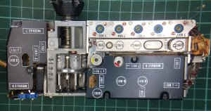
The TR-PP-11B is a French military hand held radio designed in the early ’60s. I came across one at the MDRC Hamfest this month and couldn’t resist it. The radio is also known as an ER-62B and a TRC-766. It’s fully transistorised, although of course, they are early transistors. It is very nicely constructed, the whole radio block comes out of the case quite easily as it is held into the case with the channel selector shaft and one screw.
The radio covers from 47 to 57 MHz FM with a power out of between 500-800 mW.
The radio block comes apart in two pieces, each radio subsystem is in a module and most of them unplug for ease of servicing. The channel selector is a mechanical wonder. Changing a channel turns a turret loaded with 6 crystals. One crystal is used per channel. The channel selector also tunes a 6 gang variable capacitor and a permeably tuned antenna loading coil. The mechanical force to do this comes from the way a channel is changed, the knob must be lifted out, turned and released. The retracting of the knob aided by a strong spring then pushes on a set screw per channel which rotates the tuning capacitor.
When I powered up the radio, I found that the receiver was not working and the transmitter was drifting about 500kHz low on each of the six channels. This was sort of expected for the price I paid.
There were some well written articles on the web about the radio, including an alignment guide, although a schematic could not be found. I contacted the author of alignment guide and he graciously sent me a copy of the schematic from the manual.
Armed with a schematic and aided by the modular construction, two problems were found. The 11.5 MHz IF module was not working. This was verified by taking it out and powering it up separately and feeding it with an 11.5 MHz signal.
Unfortunately, this module has a soldered shield around it which had to be removed. Powering it up again without the shield revealed that one of the four transistor stages was not functioning. The transistors are PNP and the modules are negative earth, so things look upside down. The cause of the fault was a dead AFY47 transistor.
The_transistor must have died of old age as it is well isolated from the outside world. This transistor was replaced with a 2N3906 (as there were a few in the junk box). When re-assembled, the receiver sprung to life, although the demod was slightly distorted.
This leads to the other problem. The transmitter and receiver share a common crystal discriminator. On receive, the discriminator demodulates the FM. On transmit, the discriminator is used to stabilise a Voltage Controlled Oscillator running on 11.5 MHz. This VCO is where the modulation is applied. The output of the VCO feeds the discriminator and an error voltage steers the VCO to 11.5 MHz. The VCO is then mixed with the single channel crystal oscillator to produce the transmit frequency.
The crystal discriminator is 35 kHz high for some reason. This means that the VCO is locking high and the TX frequency high. On receive, the discriminator is slightly off the IF frequency and causing distortion.
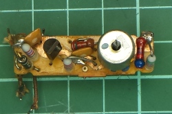
The discriminator is a sealed module unfortunately! The module was removed and then the can was carefully separated by repeated scoring of the solder sealing on the underside of the unit. After a while, the bulk of the solder was removed and the can prized off. Everything looked pristine inside the module.
Just to make sure, the discriminator was swept again in 1kHz increments using a generator and DSO to double check that it was still off frequency. This was confirmed.
After checking all the components for physical damage, the trimmer capacitor was retuned for the correct frequency at almost full mesh.
Maybe the crystal had aged ? I didn’t check the component values though.
The diodes were replaced with AA143 germanium diodes just in case they were faulty. It didn’t change the frequency though.
The discriminator lid was then tacked on with solder incase it had to be removed again and the radio re-assembled.
Its working fine now although power output is about 400mW on all channels, it probably needs a full alignment now.


Like. Radios of this era were a cohesive meld of mechanics and electronics. The electronics modules were built around the physical constraints of the mechanical parts. Rugged, modular, serviceable. Good luck with ‘le problème discriminateur’.
Yes Paul, it’s an impressive mechanical arrangement. The discriminator might be a challenge!
When i was in the French army in 1971, I used one those almost everyday. It brings me a lot of memories… Thanks for posting..
Marcel w5bjv
Do you have the extra handset connection schema ?
Hello, Because I have 2 of this type radios and was searching for a suiting battery I camen on your ver intersting site! Do you know were I can buy 2 baateries? Thanks for your reply. Kind regards Bart
Hi Bart, I did not find a battery that was an exact fit. I ended up using a 3 cell LiPo from Hobbyking and made some padding so that it did not rattle around in the case.
Hello, Would you still have the schematic or manual of the TR-PP-11? I recently bought a couple of these…
Thanks!
Patrick
ON8PDY
Hi Patrick, I have sent you the schematic.
Thanks a lot! You’re one of a kind! ON8PDY Belgium
hello my name is lionel I am french I am passionate about military radios I am looking for the diagrams for a prc766 or a trpp11 I saw that you have them would it be possible to provide me with a copy of these diagrams I will give you my address Internet
le-coin-earl@orange.fr please excuse me I go through a translator thank you in advance
Hi Lionel, I have sent the diagram to you.
Hi Glenn,
Would you be so kind to send me that TR-PP-11 schematic. That would be cool. Thanks. Yves ON6YD.
Thank you so much Glenn. I have received the schematic.👍
Hello, would you like to share the schematics of this radio? I recently bought one and it’s always good to have as much info on hand in case it’s needed.
Kind regards,
Rens
Hello, thank you for the information on the little French banana. I have one, which does not work. This one is marked in English. Would it be possible to have a copy of the circuit diagram please, so I can try and get it back on the air?
Thank you
Andy G7BAV