LoRa is a newish Internet Of Things communications technology. It promises long range (LoRa), transmits a small amount of power and is designed for sensors that may need to operate from batteries for very long periods of time. The air protocol works at very low received signal levels, with down to -148 dBm claimed with low data rate transfers.
There are several LoRa modules available for very reasonable prices from Ebay. I purchased 3 x AIThinker RA-02 modules for $20. These modules use the Semtech SX1278 chip which packs in an amazing amount of functionality. The module is capable of +17dBm transmit, with a boost mode for +20dBm (100mW).
One of the LoRa bands is 433MHz, in the 70cm amateur band. With an interest in a low power GPS tracker that could be used as the “last mile” for APRS and hiking, a test transmitter and receiver were designed and assembled.
LoRa is intended to work in a network topology with nodes that talk to field units (LoRaWAN), but there is a peer to peer mode using the LoRa protocol that has been made available by the Radiohead driver collection. I used Arduinos for the control side of things as there are many drivers and sample applications available. The GPS is a UBlox 6M unit, not the smallest, but works well.
The system was set up for a 125kHz bandwidth and a spreading factor of 11, which gives a data rate of 500 bits/sec. Initially, I tried a spreading factor of 7, giving a 5000bit/sec. data rate and this worked for a couple of kilometres with the receiver sitting on the car dash.
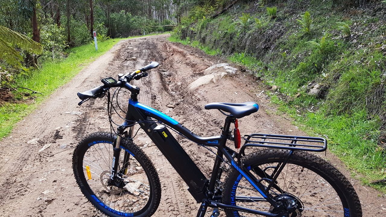
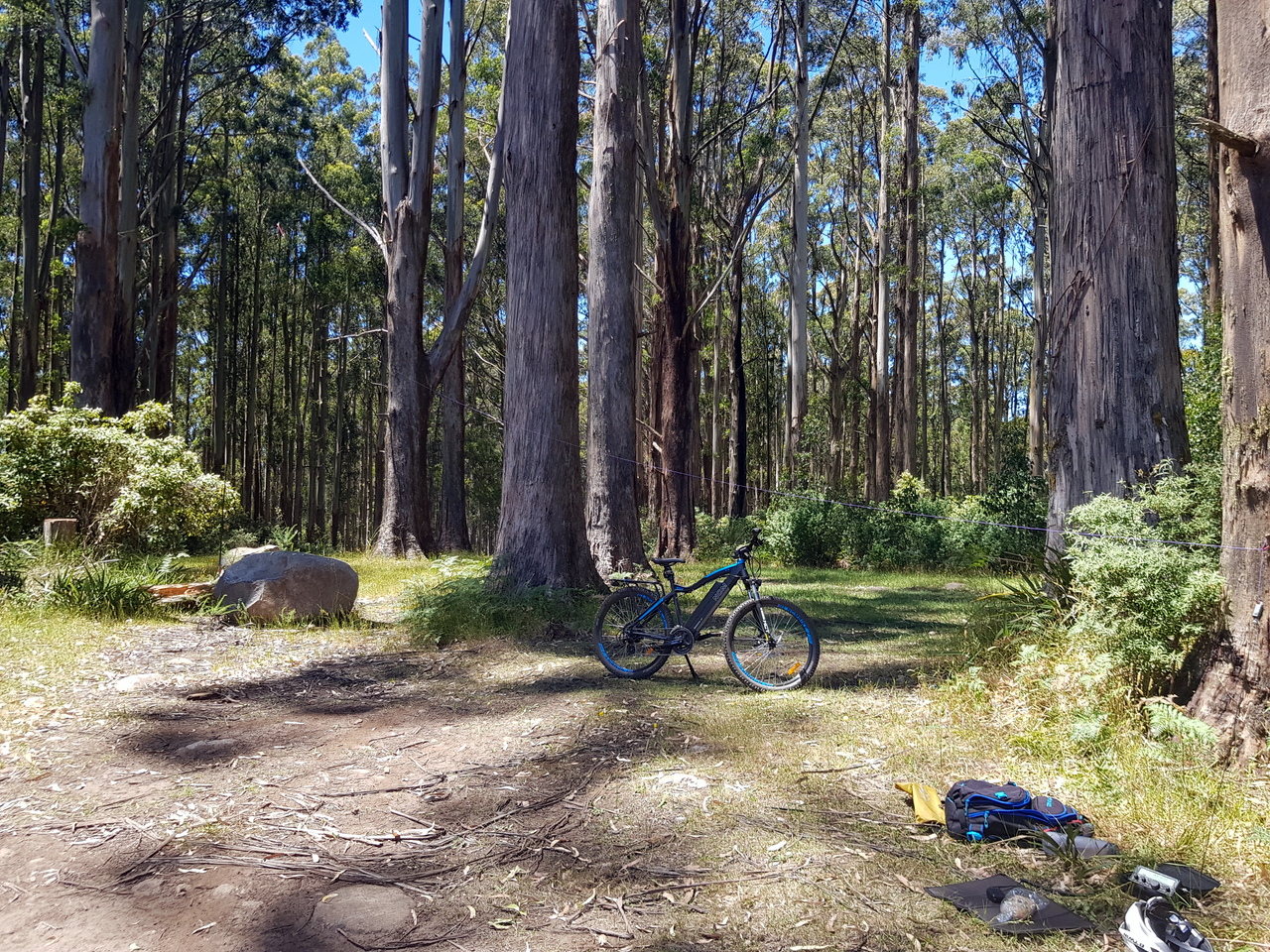
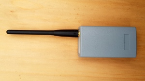
For a more controlled test, I set up the transmitting unit in the back yard connected to a mobile whip that was about 3 metres above the ground. The receiver was packaged up in a small speaker enclosure and fitted with an LCD display so I could see the decoded packets.
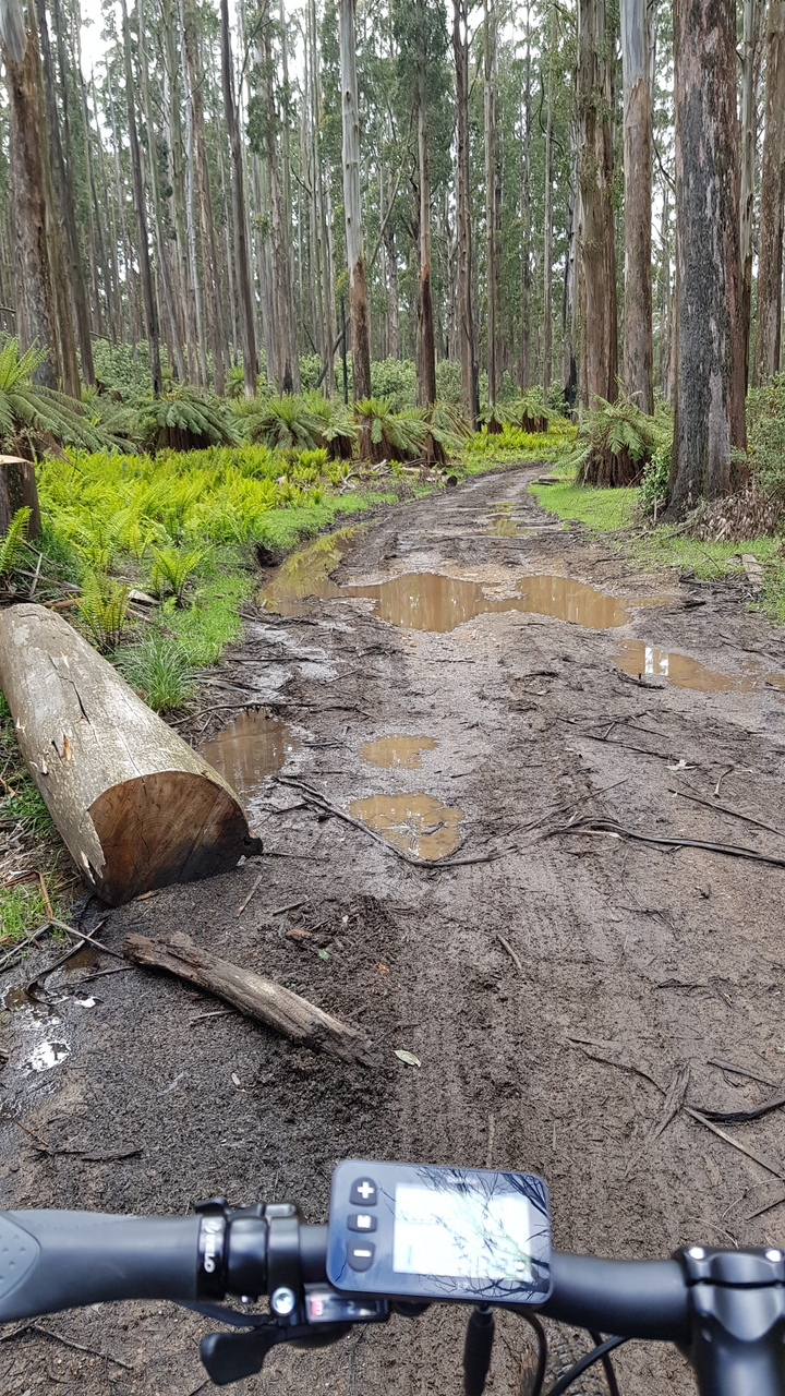
I went for a ride on the bike with the receiver and chose a distance 5km from the transmitter that was non line of sight to see what would happen. To my surprise, packets were decoded, a few were missed depending on antenna orientation (a 70cm portable rubber duck).
Here is an elevation plot of the radio path:
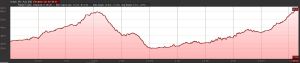
As you can see, it is not line of site.
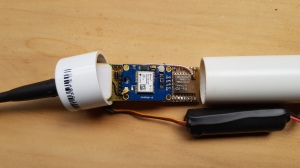
Here is the GPS tracker:
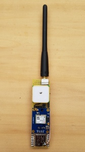
GPS Tracker
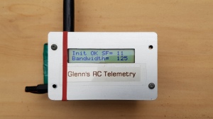
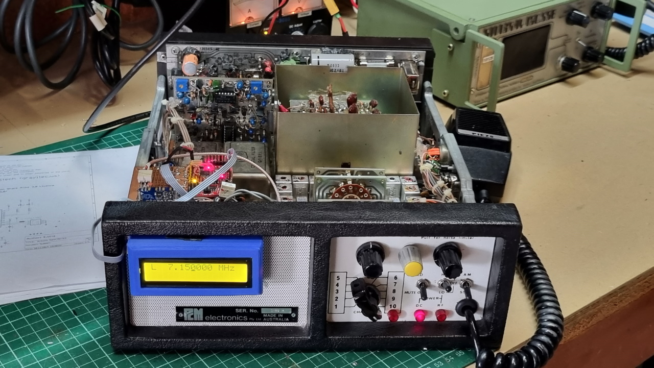
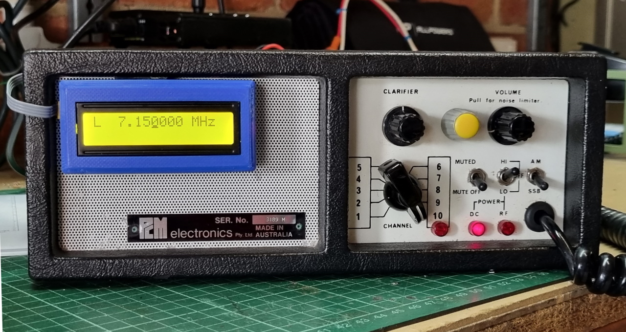
LoRa Receiver
Here is the receiver:
Power for the tracker is supplied from a single 18650 LiPo cell. A 3.3 volt supply is used for the Arduino Pro Mini, Neo 6M GPS and RA-02 LoRa module.
To save power, the GPS is powered up every minute at the moment for testing. A REG103 LDO regulator with shutdown is used for turning off the GPS receiver and RA-02 between transmissions. The initial cold fix takes about 30 seconds inside the house. Subsequent warm fixes are very fast at about 2 seconds.
With the Arduino sleeping between the 2 minute GPS reports, the cell should last about 15 days. The idle Arduino Pro Mini sleep current @ 8 MHz is about 2 mA. The GPS uses about 60 mA and the LoRa transmit, about 120 mA. It should run for more than two weeks hours on a 2500 mAh cell (providing GPS signal available, if not it will spend longer searching). After a warm start, the GPS only takes a couple of seconds to acquire.
With the LED removed and the regulator bypassed, the sleep current should be even lower.
Tracker packaging
For the moment, the tracker is packaged up in a section of PVC pressure pipe with the cell. This is quite robust and water resistant although not very efficient in terms of space.
If I can source a robust enclosure of the right dimensions, it could be much more compact.
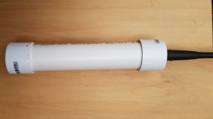
PVC Pipe Housing
The housing turned out to be far to big, so I found a standard ABS enclosure that was about the right size and rebuilt the board to fit. Unfortunately the 2500 mAh cell was too big for the enclosure, so I had to settle for a 1000 mAh cell with a rectangular footprint.
This cell fits very well, but the run time is now reduced to about 1.5 weeks, assuming a report time of 3 minutes. The idle current has dropped again by reducing the bleed current from the Arduino port pins to the LoRa module. The port pins are now all set low before entering sleep mode. The idle current is now sitting just over 1mA.
New smaller case
Here is the path profile of a GPS report from the tracker when the antenna was a mobile whip on the car and the receiver antenna, a J-pole mounted at roof height. This one must be an exception as the path is not line of sight.
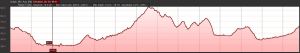
Link Path of approximately 10km