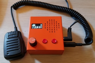
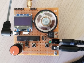
This build is based on the interesting design by Guido, PE1NNZ. The transceiver originally used the very successful QCX as an initial platform, but it now has it’s own life and there are several scratch builds using dedicated PCBs on the forum.
An Atmel ATMEGA 328 is pushed close to the limit in an SDR application processing SSB IQ from a Tayloe IQ detector. The speaker audio is supplied directly from the 328 pins as PWM. So no audio amp is required.
The transmitter uses a class D or E PA and implements Envelope Elimination and Restoration (EER) to deliver a highly efficient effectively linear power amplifer.
The implementation does have several compromises, however, running in a simple 8 bit processor with 10 bit A/D convertors.
Refer to the Github page for design details.
This build presently uses two boards, the UI and processor and the RF board in a stacked arrangement connected by headers. A test PCB was put together for the RF side, with the intention of experimenting with the design. The processor board was built using proto board.
The unit all boxed up measures about 7.5 x 8 x 3.5 cm and hopefully could be used on a SOTA trip to keep the weight down. It was painted bright orange so as not to lose it!
The PWM speaker audio worked fairly well on an efficient speaker but not so well on a small 50mm speaker. An LM386 amp was added to boost the volume to useful outdoor SOTA levels.
The RF board ended up with lots of links and suffered from changing chips and experimenting. I might do a final board, but there are others now doing a pretty good job of boards on the UCX forum.
To speed up the build, I used an Adafruit Si5351a breakout board, although this uses a 25MHz clock necessitating a def change in the software and some hardware changes.
So,how does it perform?
The RX audio sounds OK, I had some problems keeping the PWM frequency out of the extra audio stage despite additional filtering. There is some residual hiss that is quite noticeable on low volume settings. The Tayloe detector has spurious responses at odd harmonics, so it’s relying on the transmitter LPF to reduce these. A BPF or tuned bifilar toroid like the QCX would improve selectivity.
There are regular “pops” on the receiver that can be eliminated by selecting 13dB attenuation in the menu at the cost of some sensitivity.
Others have had problems with OLED display noise getting into the receiver, although none noted on this build. Good supply rail bypassing and grounding is essential.
The transmit audio is quite intelligible, although does sound a bit edgy. The transmit spectrum looks just clean enough for amateur use with harmonics and spurs around 50dB. I have made some SOTA chaser contacts successfully into NSW with it. The Transmit power is around 7W, this should be reduced back to 5W as it’s marginal with the design at this level.
Considering all the above, on a summit in most cases it is probably ok, although you might get some comments on rough TX audio quality.
In summary, it’s a pretty amazing minimalistic SDR design and squeezes almost everything out of the processor. I look forward to an implementation on a more powerful platform with higher A/D resolution with more speed and bits.


Fascinating. A step into today’s generation of simple, minimal, small low power SDR transceivers that can be reliably homebrewed without sophisticated tools.
What would it take for better performance? A Teensy perhaps, wider ADC/DAC, other things?
Paul VK3HN.
Maybe a Teensy 4.0+, it has been suggested on the forum numerous times, possible with a codec board. I think the Teensy 4.0 has a 12 bit ADC (12dB better than 328?). A 16 bit ADC would be nice.
There are external ADCs on breakout boards that could be used and to extend the signal handling capability of the MCU. It won’t be long before a really good combination arises.
hi… I like to try these projects with oled , can you share some information please..
email me @ danieldwi69@gmail.com
thanks so much
hi… I like to try these projects with oled , can you share some information please..
email me yc6lhg@gmail.com
thanks so much
Hi Herman,
Have a look here for detailed information, there are board layouts, schematics and the software is on Github.
https://groups.io/g/ucx/files
https://github.com/threeme3/QCX-SSB
Cheers,
Glenn.
any tips on where the single plug mic is being sourced – I’m trying to find one for the chinese clone
I sourced the plug from Jaycar Electronics in VK3. The mic uses a 3.5mm TRS, but Jaycar have TRRS as well.
There is some info on using the OLED that addresses the noise that display generates, remove the 2 caps of the charge pump and supply a regulated 9v to Vcc and the radio becomes MUCH cleaner in the audio output. I’m sure the other end of the signal improves as well. I haven’t finished any of the builds I have started as parts are getting harder to source but I’m still trying to get a working unit ready for the testing part along with all the stuff that will be needed to test. Now from what I have seen on the OLED’s there are different displays sold and the Vcc and Grnd are reversed on some so you need to be careful to get the right display for the radio and be sure your display has a transistor on the board, with that display it should be C3 and C4. You use a T092 Vreg, 9v and 2 .1uf caps on the input and output and can piggy back a small board onto the top side of the OLED board, run a jumper from the output to the far side of C6 from the 4 header pins and run a wire from the input of the Vreg to the 12V supply.