After doing a SOTA activation recently with VK3ZPF using only 5 watts from the FT817, thought it would be a good idea to build a lightweight amplifier that can be backpacked around. For power, will use a lithium polymer RC type battery back of around 3000mAh capacity with 3-4 cells. This should give up to 30 minutes of transmit with SSB duty cycles at a power level of around 50Watts. The design is based on a design by W6JL and uses low cost IRF2Z24N hexfets (~$1 ebay). The binocular core was also obtained from ebay. The change over relay and other toroids came from minikits.
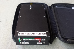
The finished amplifier after a coat of primer and flat black:
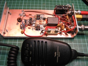
Here is the amp with the FT817 mic for an idea of size:
I couldnt find a box of the right size for the amp, so ended up making one from aluminium angle and sheet, its a bit rough but tough enough. 
 The amp has a low pass filter for 7MHz installed and puts out about 60W from 13.8V and 45W from a 3S 2200mAh RC Lipo pack. It stays quite cool considering I used minimal heatsinking to keep the weight down. The 5mm thick aluminium base plate of the amplifier is the heatsink. A 60amp RC connector is used for DC power and a 3.5mm jack is used for TX key from the radio.
The amp delivers good power at 14MHz (45W @13.8V)but requires another filter. For display of DC volts, PA temperature and RF out, an LED bargraph is used. Was initially going to breadboard up a PIC processor to drive the LEDS, but a small arduino board was only $9, so this was used. The board is very flexible with ample analogue inputs. Arduino is an easy platform to write software on.
Metered mode is selected from a pushbutton and an LED indicates the current mode with on/slow flash/fast flash/off. I was worried that the Arduino might cause noise on the HF bands but it was not a problem.
The power on/off switch kills the bias to cut the fets off and also disables the relay and Arduino (not shown).
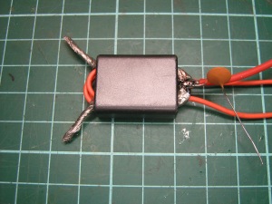
This is the binocular core for the output. The primary is made from RG-58 braid and the four turn secondary is wound through the braid. 


The primary connects directly to the tabs on the FETS with solder lugs.
It is a bit tricky to put together using normal insulation on the secondary as the heat from the soldering can melt the secondary insulation. A better approach would be to use silicon insulation on the secondary. Several toroid cores could be used to replace the binocular core.
Another view looking down at the amplifier. The two toroids at the right are part of the low pass filter. The changeover relay is top right.
The Arduino controller is not connected up in this photo. It has connections to RF sample of BNC connector, temperature sensor on one PA FET and DC supply.
Amp alongside FT817. The unit is a pretty good size for portable work, and could be made a bit smaller if need be. In this build, I wanted to make sure there was enough heat sink in the chassis traded off with weight and have enough room for the Arduino controller.
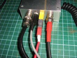
Connectors at rear of amp. note that a couple of adaptors are used on the DC connector.
Update 2016-05-07:
Its been about 4 years now and this amp has been dragged around a few mountains. Amazingly, it is still on its original set of Mosfets, despite some bad antenna matches. It now has a slide switch on the top that selects either the 40 metre or 20 metre low pass filter. Many of the recent activations with it have used a 4200 mAh LiFe pack which holds up at 12 volts nicely.
 The switched 40/20 metre low pass filter is a bit untidy but it does work pretty well. Output post filter @ 13.8V is about 55 Watts on 40m and 45 Watts on 20m.
The filter is mounted on standoffs from the base of the amplifier and straddles the output transformer. A slot in the top cover allows the switch to change band. The filter caps are SMD, the 40m caps are TDK 500V 470pF at either end and 2x 470pF at the centre junction. The 20m caps are AVX 250V with 180pF at either end and 330pF at the centre junction of the inductors.


Good gain for a small amp. Like the design. VK1DA
Well done, i just purchased a commerical PA unit. I now feel I too should have hombrewed one. Time is always the factor!
Colin VK2JCC
Pingback: Mt Donna Buang SOTA VK3-VC002 | VK3YY
Pingback: Federation Range SOTA VK3-VN003 | VK3YY
Pingback: End Fed Half Wave Matcher Version 3 | VK3YY
Pingback: Transceiver for Backpacking | VK3YY
I would like to make this set up to go with my 40 meter homebrew rig.
Can I get more info on this.
Paul
KA9UMG
Hi Paul,
If you supply your email address, I will send a copy of the article that I worked from.
Cheers,
Glenn.
pmielnicki@comcast.net
My email is pmielnicki@comcast.net
Thanks Paul KA9UMG
Hi Paul,
I sent the article a week or so ago, maybe you didnt get it? Will send again.
Glenn.
I would also Like a copy of this article.
Thanks!
73’s
John
KF6EFG
Hi John,
There is a link in the posts at the end of the article. The link is http://carnut.info/W6JL_50W_pa/W6JL_50w_PA.htm
Cheers, Glenn.
Thanks Glenn, I missed the end of the thread!
73’s
John M
KF6EFG
Hi, very interesting project and well put together .I would like to make this set up to go with my 40 meter homebrew rig.( ILER 40 EA3GCY)
Can I get more info on this.
Tiziano IW0FPN
iw0fpn gmail com
Hi Tiziano, I have sent you the article.
Cheers, Glenn.
Have resent it, the attachment is 6MB, could it be too big? Will also send via Gmail.
Pingback: Mt Toorongo Range and Mt Horsfall | VK3YY
Hello.
How much is the current drain at full power/quiescent current ? I have just built a 25 w amp for 80 meters with irfz30. I used just one fet to keep the current low for portable operation. My amp works at 160, 80 and 40 meters, but i have only 80 m filter now.
Homebrew isn’t dead. You have built a very cool looking amp!
(the processor is a bit overkill imho)
The quiescent current is a few hundred milliamps. It draws around 9 amps at 40 watts output at 12.0V. There are some DC voltage drop losses across the fuse that I need to fix. One fet would work well for portable. The trick will be to make switchable filters in a compact configuration. The processor probably seems overkill, but the board was prebuilt and compact, so a fast solution.
Hi Glenn,
could you please send the article to my email address, please? s54mtb _at_ pavlin.si
TNX!
Hi Markoo,
I have sent it….
Glen,
Nice work! Thanks for taking the time to outline your project here. I to would like to read the article you referenced above. Could you send a copy my way?
Thanks agin,
Jim
KB9LTW
jn3000jn@yahoo.com
OK Jim, have sent it.
VK3YY Hi , as the other friends i also asseble such as mosfet power ampliers. 20, 30w power. I used irf510, 530, 840 & irfz24n . All have good result. And used also irfp250. I wonder the project. Is it possible to send me the circuit and the others as pcb picture? Thank you my friend. TA3IHD- Turkish radio amateur. Look qrz.com….
hdyasa@ttmail.com
Glen
Nice work, can the amp do 6m ?.
Would like a copy of info on the amp please.
73’s
Barry Salt
VK4BAS
Hi Barry,
The amp wont do 6m, it drops off quite a bit in output even at 21MHz. Will send the article.
Cheers,
Glenn.
One way you will get 50 Mhz out of this basic design is to replace all the magnetics with type 61 ferrites and use the RD16HHF1 TO220 device x 2. These sell for about 5 USD each from reputable sources. This will get you 20W (Class C bias) or around 16W class B linear only if you want to stay within the limits of the devices. The OPTransformer core would need to change to two off 61-002 cores (about 6 USD each – The Toroid king in Fl has them as do Amidon,) in series – to do this cleanly you would need to use the copper or brass tube method of constructing the primary. (Unfortunately the 61-002 has a 6.7mm hole size which means you would have to find 1/4in Cu tube and shim it with solder tacked 0.25mm or so shim if you can find it).
The 61-002 is slightly larger than the 43-7051 – see the Amidon site for example for dimensions in archaic units.
I suggest two cores in series based on page 89 for the Fair-rite corp datasheets from the 14th Edn hard copy, which compare at type 43xx 102 core and a type 61xx 102 core and shows that the single turn impedance of the type 61 is just half that of the type 43, regardless of the AL values you will find elsewhere (see the Toroid King site for these if you do not have them available). I have a sneeky suspicion the ALs have been factored from type 43 to type 61 cores based on the relative permeabilities only.
Remember that the RD16 device has a completely different pin out to the IRF24s too in order to get the source pin and tab connected for thermal reasons , so PCB designs would need rework (fairly minor ). The RD16s can be paralleled and driven as if a single device and in fact driven from the same bias circuit on a 2 + 2 basis – I have a Japanese ham design on file that did that successfully, complete with photos. If the PCB has the devices at the edge of the PCB (see French design example I posted below ) then you can fold one through 180 degrees and pack the tab with a copper or brass strip and then clamp it through to the heat sink. The clamp bar needs to be Cu or brass too as this part will be a major dissipator part.
MITSUBISHI RD15HVF1 would be a better device for 6m operation and will give more power out at VHF , however if you operate VHF devices at HF, ie you construct the amplifier as a dual band for instance, you may find the device gain is so high they become unstable.
if you need more information or the Japanese schema –
Engstr
at Netspace dot net dot au
Hi
Very nice project, nicely done. I am interested in putting it togeder can you send me that article as well please.
Thanks Lubo M0LMI.
Sent!
Great project Glenn!
could you flick me the W6JL amplifier article please?
Just getting serious about sota and sometimes my 817’s 5w could use a boost 🙂
all the best
Ian
—
Pingback: SOTA New Year Rollover 2014-2015 | VK3YY
Hi Glen could you send to me the w6jl amp article please and any board layouts,circuit dis act.
73’s
Barry VK4bas
Pingback: Yet Another Amp for the 817 | VK3YY
hello …
I would like to make this set up to go with my 40 meter homebrew rig.
Can I get more info on this.9a3xz,Mikele
Hi, I also built this amp up, but had a PCB made for it from a ebay vendor. I didn’t need the switching of LPF on board so dispensed with them. I also modified the input transformer for a better match.
I have a pcb layout here if anybody is interested for DIY. (NB I have none of the actual PCB’s left)
http://carnut.info/W6JL_50W_pa/W6JL_50w_PA.htm
glenn
vk3pe
There is a link to this amplifer document on a Google search. I found it here
https://www.google.com.au/url?sa=t&rct=j&q=&esrc=s&source=web&cd=68&ved=0ahUKEwiDtOXP8rHKAhWRC44KHenoDS44PBAWCDowBw&url=https%3A%2F%2Fxa.yimg.com%2Fkq%2Fgroups%2F87064595%2F1422084143%2Fname%2F2009%2BHOMEBREW%2BCHALLENGE%2B50%2BWATT%2BAMPLIFIER%2BENTRY.doc&usg=AFQjCNEFlCwT1JQIpWk88dZmYHhAxwfd1g&sig2=3DwZTgHzBzRRl3opLR908w&cad=rja
Regards
glenn
vk3pe
Thanks Glenn!
Pingback: W6JL 40m amplifier | vk3jbl
Hello Glen,
Great work – This is exactly what I have been looking for!
Would it be possible to get more info please?
2e0fvv@gmail.com
Thanks in advance,
Mark
Pingback: Mt. Howitt VK3/VT-001 | VK3YY
Pingback: Return to Mt Gordon VK3/VN-027 and Mt Strickland VK3/VN-030 | vk3hn
Hi Glenn…nice homebrew PA project. I want to try to build one..Would you send more detail about this nice little PA..My Email 9m2rmt@gmail.com. Thanks in advance..
Hi, try this link for more detail. Let me know if it doesn’t work.
https://www.google.com.au/url?sa=t&rct=j&q=&esrc=s&source=web&cd=9&cad=rja&uact=8&ved=0ahUKEwiOk7vGvbTKAhXSC44KHeH5BicQFghOMAg&url=https%3A%2F%2Fxa.yimg.com%2Fkq%2Fgroups%2F87064595%2F1422084143%2Fname%2F2009%2BHOMEBREW%2BCHALLENGE%2B50%2BWATT%2BAMPLIFIER%2BENTRY.doc&usg=AFQjCNEFlCwT1JQIpWk88dZmYHhAxwfd1g&bvm=bv.112064104,d.c2E
thank you..I successfully build the PA….and goes on air…the heatsink become warm…wonder what is your bias setting..mine 3.5v..should I increase or remain there..
thank you..
Hi, I adjusted each pot for 100mA idle current per FET
Bit confusing with two Glenn’s. Anybody interested in my take on building the Amp, check here. http://carnut.info/W6JL_50W_pa/W6JL_50w_PA.htm
NOTE, I did not fit the switching circuits per the original as not required for my useage. I did find the input SWR above 40M was not very good, so used a different transformer wound on a Balun core instead. (details on my link)
There is a link to a pdf file of the layout, for my PCB version near the top of the link.
I did have some pro made pcb’s but they have all gone to other builders.
glenn
vk3pe
Thanks Glenn, some great information there. Yes, confusing with two Glenns. The input VSWR on my unit is also higher on 20m.
Hello.
How is controlled by a relay in the amplifier?
I have already finished layout and wants to hook up to my radio FT817.
Regards Kris SQ9IWR
Hi Kris,
The front panel on/off switch provides switched DC. The relay is driven from the active low FT817 TX output, relay coil 1 to switched positive supply, relay coil 2 to FT817 key line. There is a catch diode across the relay. The switched positive supply also switches the bias on for the FETS. Regards, Glenn.
Glenn,
for information of other possible builders, there is a beautiful implementation of this basic design at
http://www.rotilom.com/F6IDT including Schematic, PCB LO and assembly photos.
The data is all in Fr but easily translatable. He (Pierre ) includes and ROS ie VSWR circuit independent from the main PCB. Bias control diodes not included, at I recall but Pierre used a humougous heat sink probably around 2.5 Deg C per watt I would guess. Still , at 45 W dissip or so she is going to get warm on key down over 5 minutes.
He has gone to a lot of trouble to make the CT of the OP transformer exactly electrically symm. The word on the street is that CT OPTs do not work well in terms of signal symmetry but my guess is that it all depends on the physical build quality.
The COR circuit obviously has to be disabled for CW and I have heard that COR switching is technically banned in the US, perhaps only for commercial amplifier
FYI My web protection (Blue coat) gave a warning about the Rotilom site but after assurances from Pierre I turned it off and no issues arose. I suspect that the WWW site simply had not been rated as it was a bit obstruse.
regards Tim F/ NZ
Hi Tim, that is a very nice build, the layout is extremely neat. regards, Glenn.
Pingback: 20082017 – VK3/VC-018 Mt Bunnyiong | VK3ARH
Pingback: Homebrew 50 watt amplifier for 80-17m (W6JL) | vk3hn
I am interested in homenrewing this project.
Can you provide me with the source code for the nano module for controlling the device
PM sent.