
As the new 10m and 6m SOTA challenge has now started, it was time for a little more gas from the 817. Looking around on the web, the most successful solutions at the moment are based on the RD16HHF1 FETS. They are available for a very reasonable price and deliver power at 12V.
I was looking for a slightly higher power solution to complement the existing 40m amp which will do a little over 50W on 40m @ 13.2V, but the RD16HHF1 FETS in an amp can cover a pretty wide range of frequencies.
Having a look around, the amp was based on a design by TF3LJ/VE2LJX. David, VK3IL also made a nice amp for his KN-Q7A based on this design.
The plan was to use this amp initially on 10/12/15 metres and a single compromise low pass filter would probably cover these three bands.
A PCB was quickly made to try things out using the toner transfer method, but I forgot about it and left it in the etchant too long. The result was a slightly over etched board with some pits.
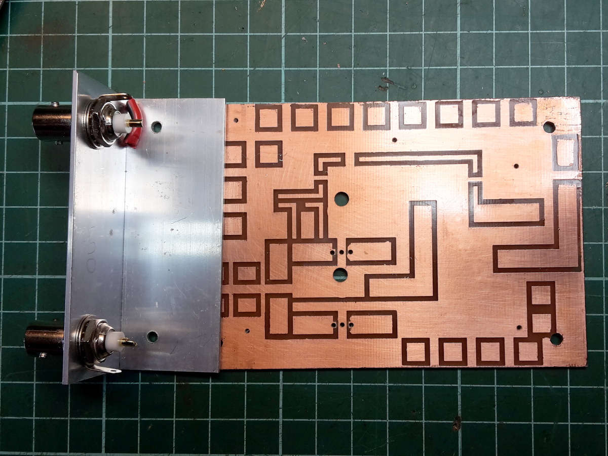
Slightly over etched!
The mechanical layout is similar to the 40m amp although it is shorter. The base is a piece of 5 mm thick aluminium sheet 75 mm x 112 mm and some 30 x 30 mm aluminium angle is used for the ends to mount the front panel and back panel. The top cover is made from a piece of 1.6 mm Al sheet and two pieces of 30 x 30mm Al angle. The base provides most of the heat sinking and should be OK for low duty cycle SOTA. The PCB is mounted about 4mm above the heatsink on standoffs soldered to the PCB. This leaves enough space for the FETs to be mounted between the PCB and the base plate.
On the 40 m amp, the voltage and power out display used an Arduino driving an LED bar graph. While this works fine, it’s overkill I guess. The Arduino only cost something like $10 so it was an economical solution. This time I chose an LM3914 dot / bar driver and an LED bar graph. This is a little cheaper than the Arduino and a little simpler. On the front, one slide switch is for power and the other for selecting the meter.

Amp DC/RF Bar Graph and C/O Relay
I learnt from the other amp that toggle switches stick out too far for portable work and get damaged.

Prototype Amp Layout

Rear connectors

Front View
Some_experimentation was done with low pass filters. From the ARRL Handbook, a 5 element Chebyschev filter was chosen initially to see if it would provide sufficient attenuation for the three bands. A filter was selected with Fco of 30 MHz but when built and swept it came out too low. The cores used in the filter were T50-6. Just to test the cores out, I made a lightly loaded tuned circuit on 20 MHz using the core parameters and found this resonated about 20% low. The cores were purchased from Ebay and am wondering if they were genuine cores? The filter values were changed to compensate and the sweep was as expected. Being push pull, the second harmonic should be down, so the filter is only working on third harmonic on the 15 m band. 10 and 12 m should be fine.

Low Pass Filter
Spectrum analyser plot for the amp on 28MHz @ +44.4 dBm below:

28MHz, 2nd Harmonic -60dB, 3rd 64dB
The output transformer was critical, so I experimented with this and tried several configurations and winding material. The final transformers used RG174 braid for the 1 turn primary and insulated wire with 17 strands of 0.14 mm wire for the secondary. This worked nicely from 7 MHz to 50 MHz (with no low pass filter). Later a switched low pass filter that includes 50 MHz will be added.
The DC connector uses a Hobbyking XT60 male which has a teflon insulated positive pin going through the back panel that is soldered to a PCB glued to the inside of the panel. This has worked well on the other amp. The PTT is taken from the 817 and feeds a PNP transistor base via 10k resistor. Collector is to ground and emitter to the relay. The other side of the relay goes to switched DC and of course a flywheel diode across the relay.
It’s work in progress, but post filter @ 13.8V it is producing 25 W saturated on 10 m and 12 m and about 22 W on 20 m. Bias is currently 350 mA per FET, but need to check linearity.

Rear View

Front view

Hi Glenn, You are a true experimenter and I like the approach you have taken with the amp. I have picked up quite a few ideas from your blog. Cheers
John D
VK5BJE
Thanks John, hope to try it in the field soon.
Hi,
I saw this Loftur design some years back and it is amazing it works as it relies on the secondary inductance of the non driven transformer being high enough not to shunt out a good deal of the power being delivered. ( You can see this effect as you are measuring lower power out at lower frequencies , which is just the opposite of what normally happens with an RF PA). I also suspect that getting the bias right for this topology to work in linear mode but not sacrificing too much of the signal via shunting in the non driven mosfet might be some fun. Loftur does not mention this possible issue. .. as far as I recall.
Did you consider using cores for the OPTransformers that would allow say RG58 braid , even squashed a bit to fit through with the secondaries inside the braid ? that way you don’t have the B field from the primary side which is not against the web of the core fighting the field which is induced in the web of the ferrite (in terms of the flux that the secondaries see). Did you consider use of multistrand TE insulated wire to reduce the shunting effect you will get with other dielectrics when the coils are over wound? Moreover it seems nearly all TE coated wire is silver plated prior to PTFE extrusion, which matter helps with skin effect losses at HF. I found a reliable US based TE wire vendor on ebay a while back… I could measure the OD on some samples and advise if you wish. I assume that the insulation on your secondary wire is PE. PVC insulation is very lossy at this frequency and gives higher winding capacitance too over PE insulation.
I guess it is a bit late to go changing cores at this stage 🙂 ! Obviously, there is zero scope for reducing the number of turns on the secondaries.
The transformer design though shows a lot of Finnish ? lateral thinking. I am surprised the ARRL did not come up with this RF transformer idea in the 70’s. Perhaps it only works well with RF mosfets and perhaps too, it is not very scalable for higher power work. Cheers Tim F.