
This VSWR analyser looked interesting from K6BEZ. Certainly simple and low cost and probably just the thing to test the multiband SOTA antennas that I have been putting together lately. I happened to have one of the DDS modules spare and would change the Arduino module in the article to a Nano as they are compact and cheap (~$10).

Screenshot
Rather than build it on veroboard as per the article, I made a PCB using Eagle and the toner transfer process. The board is mostly SMD to keep it compact and these days SMD is easier anyway.

Analyser PCB
The board came out nicely, it is single sided and only has one link. It uses the entire bottom copper as a ground plane. I couldn’t source the AA143 germanium diodes locally, so picked up a couple of 1N34a diodes.
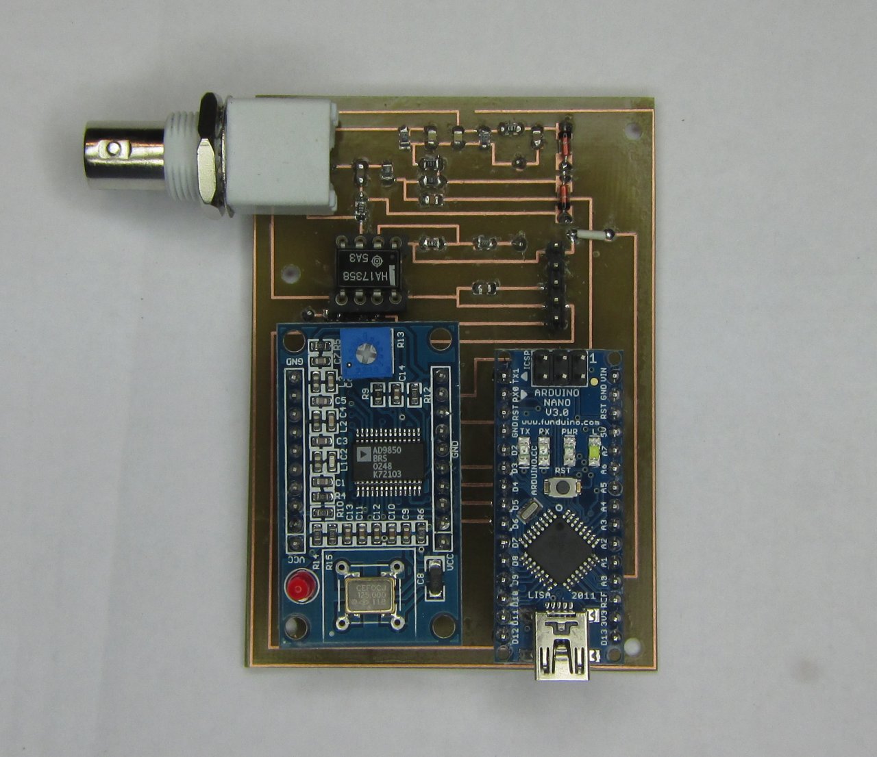
Assembled Antenna Analyser
After loading all the parts with the exception of the MCP6002, I got a little impatient and plugged in an LM358 temporarily so that I could play a little. I remapped the DDS data lines on the Arduino to better suit a simpler PCB layout. It all went together pretty well. Another compromise made was with the gain resistors on the op-amp. I didn’t have any 5k / 648 R resistors, so the gain was kept the close by using a 6k8 and a parallel combination of 1500 and 2200 R resistors (891 R). This gives a gain ratio of 7.624, where the original resistors had a ratio of 7.716. After a power up, it looked OK, so the K6BEZ analyser software was started. It connected OK, and when the sweep command was executed, you could see comms activity, but there was no display on the graph. After poking and proding, I could see that the DDS was indeed sweeping and there was a slight analogue voltage sweep to the Arduino. As a last resort, I tried an older version of the sweeper titled “Thrifty Antenna Sweeper”. This sweeper did give a plot on the graph although it did not redraw on every sweep. A dummy load was connected and there was a more or less straight line. The offset fed HF dipole was connected and the resultant sweep did sort of show dips where there should have been. I will wait until the MCP6002 arrives before doing anything else. The MCP6002 op-amps arrived today. Once installed, they fixed what seemed to be an DC offset problem where the SWR on a 50 Ohm load was 2:1. Now it seems that there is a frequency response problem with the substitute diodes (1N34A). See plots below:

No load on the analyser

50 Ohm load on the analyser

OCF antenna with 50 metre old RG58 extension
Note-that the OCF antenna used for the test was extended with a 50m+ run of RG58 coax to reach the computer, so the coax run is probably making the match look a lot better than the antenna is at the feed. Next thing is to obtain the original diodes (AA143) to see if that is the reason for the falling response. Yahoo_Group: https://groups.yahoo.com/neo/groups/k6bez_projects/info Update 2014-09-30: Beric, K6BEZ replied on the yahoo group with a fix to the aduino code to make it compatible with the newer PC sweeper software. // Send current line back to PC over serial bus
In summary, there is an unused field that has to be removed for the newer sweeper software and the FWD and REV fields are not used.
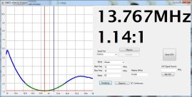
Update 2014-09-30: 1N60 diodes made a noticeable improvement over the 1N34a diodes. There is still a rolloff in the plot when the analyser is unterminated, but VSWR is now reported out to 30MHz that correlates with the VSWR measurements using a bridge.
Update 2014-10-05: The analyser was hooked up to the SOTA End Fed Half Wave to see how it looked. A 10m feed of RG58 was used. The result is pretty good. It seems to be working OK now. The antenna was originally optimised for 7.090 MHz and it is damn close in the plot.

40m End Fed Half Wave
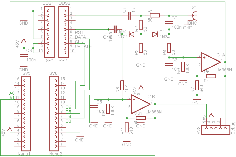
Original K6BEZ circuit with Arduino ports changed. Note R4 shown as 50R it should be 10k
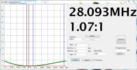
Update 2014-10-10: Changed R6 on the DDS board from 3k9 to 2k2 which resulted in an increase in DDS output. With 3k9, the output loaded to the sweeper was 600 mV p-p. With the 2k2 the output increased to 1000 mV p-p. This change increased the sensitivity of the analyser noticeably.
Some plots from the 40/20/10 metre end fed: 

 Update_20114-10-08: The PC program won’t run on my Windows XP netbook, which makes it difficult to do measurements outside.
After some software programming using processing, I have a multi-platform capable application that will at least run on the old netbook. The application is pretty rudimentary, but plan to work on it and clean it up a bit. At present it will only sweep a few pre-defined ranges as the graphing is rather basic. I am using the grafica graphing library for processing to do the plotting.

EFHW – Plot
Here is a plot from a 40m end fed half wave. The processing application is working pretty well now. I have divided the sweep into 3 bands, 1-10 MHz, 10-20 MHz and 20-30 MHz. This was pretty easy to scale. I might add the HF ham bands later.
It does run on the old XP netbook just fine.
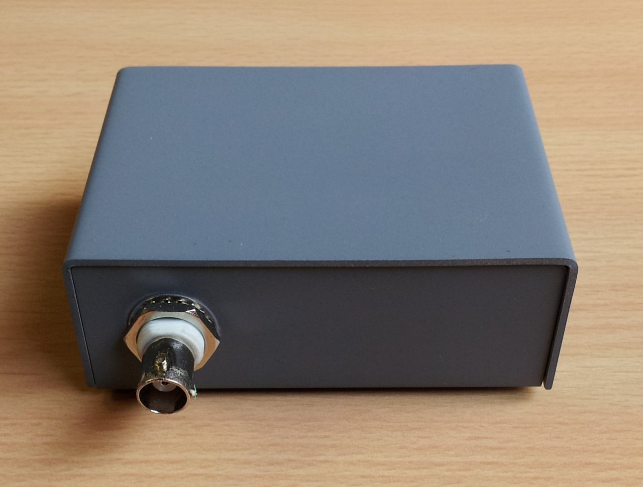
Packaged up
Update 2014-12-06: Lars, KN5UTE did a great job of cleaning up and enhancing the user interface on my processing version of the sweeper software. The com port can be selected now where as before it just chose the first com port it came across. It still won’t compile to an .exe for some reason, so it is still running out of the IDE.
The VK3YY/KN5UTE software can be found the software is in the files section of yahoo groups “K6BEZ Antenna Analyser”.
Update 2015-01-04: Received some AA143 diodes in the mail from KN5UTE, tried these out and there was a slight improvement at the 30MHz end compared to the 1N60A diodes.
I will leave these in.


I believe you omitted a 10K resistor coming out of D2 on your diagram.
Hi Richard, R2 has a 10k resistor on it, but the diagram incorrectly shows a 50R resistor coming from D1 instead of a 10k, is this what you meant?
Glenn.
Glenn, yes you are correct. I must have been a little cross eyed when I made the comment. I was thinking about making a circuit board like yours. I have added a 2.2″ TFT Display to my version to show the graph so I need to tidy up things with a PCB. One problem I have that you don’t seem to have is the vswr into a 50 ohm load is not flat. It starts out 1:1 at 1MHz and rises to about 2:1 at 30MHz. I don’t have the exact diodes but I have something close to the same. Looking at the A0 and A1 values, the FWD decrease with frequency and the REV increases with frequency. Otherwise things work correctly.
Richard – AC4T
Hi,
Thanks for sharing.
Is it possible in this circuit To measure the antenna impedance?.
(or how to measure?)
Best regards.
Murat
Hi Murat,
No it does not report the antenna impendance.
Cheers,
Glenn.
Thank you Gleen.
Looks great and simple. Could you share your eagle files or the art work…
Garry WB0NNO
Hi Garry,
The eagle file has been sent.
Glenn VK3YY.
Pingback: QRP End Fed for 40m/20m/10m | VK3YY
hi glenn,
i have just gotten my DDS module today & it appears that the ckt is working, however i am having trouble with the pc graphing. i expect that i will need to get a software development station to actually mess with beric’s VB code for the pc. i have just installed everything on an old win vista machine. the SW comes up, but it appears that the data is graphed wiht a +SWR and -freq offset, or possibly a freq compression – ie when i put a 30MHz marker on, it shows up somewhere round 21 MHz according to the plot. and when i feed my dummy load, and the reported numbers are in the neighborhood of 1:1, the plot shows a line across at about 3:1.
if i had easy access to a compiler this might be fun to dig into, but in the short term i was wondering if you would be willing to share your xp version so i could at least compare things. i have been conversing with matt gumbley about his linux version, but that one is not working for me yet either – .
anyway, assuming you are willing, i don’t know what the customary method of sharing is. you can send me a link or the executable directly. my email is larski at verizon dot net
thanks either way in advance
lars KN5UTE
Sent!
Would it be possible to receive the PCB ( Eagle)
Sure, what is your email address?
yo9nc@yahoo.com
sent!
I’d be interested in the Eagle file for the PCB also.
Thanks,
Bill
KB4Qs
Hi Bill, can you send your email address?
My email is europabill@bellsouth.net
Thanks,
Bill
KB4Qs
Would it be possible to receive the EagleCad files for the schematic and board ?
Sent!
Hello,
Would it be possible to receive the PCB ( Eagle)
Yiannis
Sent !
More than interesting. I can also send my file to the PCB.
Thank you.
ea1gvm@gmail.com
Very interesting project.
You may also send me to my PCB file ?.
Thank you very much.
ea1gvm@gmail.com
Sent…
Hello, I’m starting to build the analyzer. I have sourced most parts but I would like to se your build so if you can send any info on the project would be great (PCB, Code, bom etc.).
Sent.
You may also send me to my PCB file ?.
Thank you very much.
IZ8XTV de Mimmo
You may also send me to my PCB file ?.
Thank you very much.
domenico
domenico.grella@gmail.com
Sent!
Dear Glenn,
I would like to give a try. Could you send me the pcb file?
Best regards,
Caglar
TA2UH
Will send it later in the week.
You may also send me to my PCB file ?.
Thank you very much.
OZ1FHU Preben
oz1fhu@qrz.dk
Hi Preben,
I will sent it later in the week when I am home. Glenn
Sent..
Hi, I think I will build this analyzer top. Could you also send me your Eagle-Files? Vy 73 Sascha
Great Job. Very informative project. Could you please send me the pcb file? pattymorr@netzero.com
Sent…
Awesome. I am interested in trying it out. When convenient, could you send me the Eagle files too? Email: frank at texasthree.us
Sent…
Hello, nice work! I too used 1N34a diodes, will replace them ASAP now that I saw your results 🙂
Could you share the Eagle files? Right now my analyzer is in ‘prototype’ form, very fragile. Would love to make a PCB. Thanks!
Hi, I can send next week…. Glenn.
Can you send your email address?
jokubas.ver(at)gmail.com
sent…
Can you share the files please
Regards
ei5hrb@gmail.com
Hi, I am also interested in a copy of the Eagle files!
73’s de SM4HAK
Hi, I can send files next week.
Thanks!
73’s
Can you send your email address?
sm4hak@yahoo.com
sent….
Hi glenn veryy interessant project is iT posible that you send me the PCB file and THE programfile for the nano
Many thanks from Gerard de pd0pkg adres pd0pkg@home.nl
Sent..
Hi! Could you also send me your Eagle-Files? And the programfile for the arduino? Thanks!
73’s koaxos at gmail dot com
sent!
tnx
Pingback: ARDUINO HF Anten Analizörü |
Hi! Thank you VK3YY for a nice Project with PCB,
I´m now ready with a working ananyzer.
Others pse check that pcb and the arduino.INO file compares, I had used an INO file with wrong pin assigned for the 4 DDS control pins, in my first experiments.
should be D3 Reset D4 data D5 fu_ud D6 Wclk I learned something Again;-)
vy 73 de oz1fhu Preben
Yes, this is in the text of the blog, but easy to miss. When sending out artwork recently, I have also sent out the modified Arduino code. Thanks Preben for pointing that out.
Cheers,
Glenn VK3YY.
Hey,
could you also send me the Eagle files?
Thank you so much!
sent…
Reading thru here it doesn’t look like I ever thanked you for sending the Eagle file..
Thanks
Garry
WB0NNO
This is a great and very much needed project.
Could you send me the PCI file as well ?
Thanks very much
sent!
Hello,
very nice job! I want to try to make it. Can I get pcb and your source code for nano?
Thank you very much.
stasysa@gmail.com
Hello,
I am sorry, arduino is new for me…. Could you send me your Eagle-Files? And the programfile for the arduino nano?
Thank you very much.
Hello,
Like many of the others I am extremely interested in your source code and your Eagle-PCB Files.
Can you please send them to me?
Thanks
Steve I – vk3vm@hotmail.com
Sent!
Hello Gleen
I would be happy if I could have a copy of your sketch for the Arduino Nano.
I´m i dought why my analyzer shows the SWR mutch better than it is.
150Ohm is around 1:1.7 No matter what PC soft I use.
vy 73 de oz1fhu Preben
Hi Preben, my analyser is also out to some degree although I dont bother too much because I use it mainly for relative measurements. Mine reads about 1.6 for a 25 Ohm load instead of 2. I will send the code anyway.
Cheers,
Glenn.
Hello Gleen,
What is the current values for stable and accurate results?
1. R6/R7 5K/648 or 5K/891
2. R4 10K or 50ohm
3. diode: 1N43A or AA143 or 1N60A
Best regards,
Murat
Hi Murat,
R6 = 5k and R7 648
R4 = 50 Ohm referred to circuit in the post.
AA143 were the best and 1N60 acceptable.
Best Regards,
Glenn.
Thank you Gleen.
Hi, great stuff… VK3YY …
I would like to have the codes and eagle files…
Can you share your files on github or other code sharing sites instead of sending via e-mail ?
Also, what is yr opinion on this article :-
http://vk5ajl.com/projects/SWRBridge.php
Thanks
Hi Glenn!
Other 1n60a diode instead of any silicon diode is not good? This is not the germanium diode can I get it.
Hi Zoltan,
I had the bet results using the AA143 diodes. I have seen them on Ebay.
Cheers,
Glenn.
Very interesting project.
You may also send me to my PCB file ?.
Thank you very much.
ha6ze@hotmail.com
sent!
Hi Glenn, thank you very much * ha6ze
sent…
You may also send me to my PCB and programm file ?.
Thank you very much.
Mario
dl1gt@ish.de
Hello again.
I see that many people are interested in the PCB files. Why not just upload the files and provide the link in the article? That way it’s quicker and easier for everybody…
Also, I had the idea of modifying your design, and making an Arduino Uno AD9850 Antenna Analyzer Shield. Basically, the shield is a PCB with all the components and a slot for AD9850. The shield connects to the Arduino Uno, then you plug in the AD9850 and it’s a nice self contained unit. When you want to use the Arduino for other stuff, you just unplug the shield, and the AD9850 if you want too.
I tried to make a PCB for that, but since I don’t have experience in designing PCBs, I’m passing the idea for everyone else. Ideally, it should be a single sided PCB so that it would be easy to make at home. Then, the gerber files could be released so that people could modify it for their needs (I, for example, use SMD variant of MCP6002)
I hope you guys like the idea, and hopefully someone will make a nice design 🙂
73 de LY5NF.
Hi, the files can now be downloaded directly, it just took some time to get around to it 🙂
Nice idea about the shield for Arduino. Maybe someone will make one.
Cheers,
Glenn.
Hi is possible ha a pcb o all info for this project?73 iZ0HQS
Hi, the files can be downloaded from the links in the blog,
Cheers, Glenn.
hi Glenn not found file in filedropper.com please send me via email. tnx
Hi Glen ,
Please send me the latest version of PC – Windows software for antenna analyzer .
Thanks in advance !
73 ! de E74MG ( Sarajevo )
Hi, the files are on Dropbox. See the links at the end of the article, I just tried them and they still work,
All the best, Glenn.
TNX!
Hi Glenn, I tried using the links in this blog and they took me to the Filedropper “Sign-up” page. Nothing I did (even signing up for the free trial) allowed me access to the files. This is a great project. Could you steer me in the right direction to access the files or send to my email?
73 KE0DGP
reggiefarcher@gmail.com
Looks like filedropper is not working, so I moved the links to dropbox.
Hey VK3YY thanks for the fantastic write up. I’ve built a bread board versions and it works well. I’ve also tried out a little Processing but I’ve not got anything looking polished yet.
Do you think you could email me the file or make them available via GitHub? The links in the blog do not seem to work.
73,
Stevan (M0SCX).
Hi Steve,
I changed the link to dropbox, it should be fine now.
Glenn.
Any chance of ontaining the eagle file? Software?
Hi Adrian, there is a link on project to a Dropbox folder with the files.
Glenn
Someone had to use linux program?
Do you by any chance make these boards for sale? If you do I would be intetested
Adrian
Hi Adrian, no I don’t make these boards for sale. You could try the k6bez_projects yahoo group, someone was selling kits there.
Glenn
Ok thanks K6BEZ not making kits or boards anymore 😔
Hi, I made the circuit but not working.. what sort of voltages shd I get after the diode ? I’m use 1N34 diodes… I measued with volt meter of only 100mA after the diodes.. I find the AD9850 could not produce enough peak to peak voltage at 10m band …
thanks Steve for a great article. im just returning to the amateur radio fold after 20 years absence so ive got a bit of catching up to do ,ihave collected all the bits now but wondering have you tied all the unused pins on both ad9850 and uno to ground or just left them floating
thanks john vk5kaf
Hi John,
I left the unused pins on the DDS module and Arduino unterminated.
Cheers, Glenn.
Hi Glenn,
This project is very interesting!
Can you send all the necessary files.
Thanks in advance!!
Hi, there are links to the files in the project,
Cheers,
Glenn.
HI. Great project. Unfortunately I am a bit dense following schematics…. can you tell me why the schematic has 2 ics but the board has 1? Am I missing something? Thank you for making the board available for simpletons like me 😀 also “r6 on DDS” does this mean I need to replace a resistor on dds unit? Thankcl you very much for your effort, greatly appreciated.
73
Alan
Hi Alan, no worries, the schematic shows two sections of a single IC, the dual op-amp. It is one IC with two amplifiers. Regarding R6, yes, replacing this resistor on the DDS increases the output level a bit and gives the VSWR detector a bit more signal to work with.
Glenn , thank you very much for the rapid reply. I am learning this all as a new skill and am a bit directionaly dyslexic… As I said be for thank you for making the board available so as folk of limited ability like me can build decent pieces of test equipment. If you were in Scotland I would definitely buy you a pint 🙂
73
Alan
Has any one trialled an Arduino UNO in place of the Arduino MIcro. As I am just starting this project It would be an interesting to hear any comments.
Yes i try in arduino ONE and works very well using diodes OA90
Thanks for the feedback. I am trialing a Uno and a leonardo. I’ll see how it goes. Still waiting for the DDS module board.
I tried processing sketch, which needed grafica and controlP5 libraries.
On running the sketch ( I know nothing about processing) it reports “The function setControlFont(controlFont) does not exist. If I comment it out, it goes forward but reports errors at every “toUpperCase” and “captionLabel” functions.
What is wrong with my procedures? Do I need a old controlP5?
Thanks in advance.
Hi, am not too sure what is going on with your processing setup. What version of controlP5 are you using, I could check it against mine.
Cheers, Glenn.
another user from japan had the same problem with some functions reporting errors, after he had upgraded to Windows 10. it turned out to be a Java Runtime library incompatibility. he upgraded to the latest Java Runtime appropriate to Windows 10 and the problem self-resolved. Hopefully the same procedure will work for you.